Seismic Principles
11. What Site Class is assumed by the geologists when they create the maps for Ss and S1?
(a) Site Class A
(b) Site Class B
(c) Site Class C
(d) No Site Class needs to be assumed
Solution
Best answer: (b)
Explanation
You can tell that Site Class B is the "default" site class assumed by geologists, since the adjustments factors that take into account the effects of the soil at a site (Fa and Fv) are always equal to 1.0 for Site Class B [see Tables 1613.3.3(1) and 1613.3.3(2) in the CBC]. The best answer is (b).
Did you get this question wrong?
The book Seismic Principles, is the ultimate resource to help you as you are preparing for and taking the real exam. Chapter 3 of Seismic Principles takes you step-by-step through the procedures for classifying sites and buildings and calculating the design base shear. Section 3.5 of Seismic Principles, with Examples 3.6 and 3.7, discusses site effects.
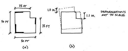
12. A one-story building in Seismic Design Category D is shown in Figure (a) below. When the equivalent lateral force is applied it deforms as shown in Figure (b).
Which of the following are true?
(a) The design forces shall be increased 25% for diaphragm connections, collectors, and collector connections (except when the overstrength factor has already been applied)
(b) The equivalent lateral force procedure cannot be used for design
(c) Both (a) and (b)
(d) The building has no penalties for irregularities
Solution
Best answer: (a)
Explanation
The steps for this problem are: 1) determine if there are one or more irregularities, and 2) determine the penalties associated with any irregularities.
Step 1 - Determine if there are one or more irregularities
There are five horizontal irregularities and five vertical irregularities defined in ASCE 7. A one-story building cannot have any vertical irregularities, so the horizontal irregularities are all that need be investigated.
The information in Figure (b) can be used to check for Horizontal Irregularity 1 - Torsional Irregularity. Since the maximum drift (1.1 in.) is less than 1.2 times the average drift (1.05 in) there is no torsional irregularity (see ASCE 7-10 Section 12.3.2.1).
This building has a reentrant corner so it should also be checked for Horizontal Irregularity 2 - Reentrant Corner Irregularity. Since the ratio of the reentrant corner dimension to the total dimension (15 ft / 50 ft, same in both directions) is greater than 0.15 for both directions, there is a reentrant corner irregularity.
Step 2 - Determine the consequences for the irregularity
Tables 12.3-1 and 12.3-2 in ASCE 7-10 point to sections that give requirements for various combinations of irregularities and Seismic Design Category. For a building with SDC D and horizontal irregularity 2, the penalty is that the design forces shall be increased 25% for diaphragm connections, collectors, and collector connections (except when the overstrength factor has already been applied). The best answer is (a).
Did this question take you a long time?
Step 2, described above, is a bit time consuming with ASCE 7, because you may have to go to several sections to investigate penalties. The book Seismic Principles, is the ultimate resource to help you as you are preparing for and taking the real exam. Section 6.17 of Seismic Principles consolidates all the penalties on one page so it it fast to check the consequences of irregularities.
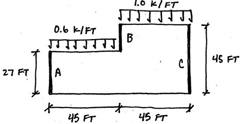
13. The forces shown below are the diaphragm design force, Fp, distributed in proportion to the mass. The diaphragm is flexible.
What is the maximum diaphragm shear (in plf)?
(a) 500 plf
(b) 800 plf
(c) 1330 plf
(d) 1500 plf
Solution
Best answer: (a)
Explanation
Since the diaphragm design force, Fp, is already computed and distributed, there are only two steps remaining in order to determine the maximum diaphragm shear (in plf): 1) compute the shear for each span of the diaphragm, and 2) divide the maximum diaphragm shears by the diaphragm depth.
Step 1 - Compute the shear for each span
Flexible diaphragms are analyzed as simply supported beams that "span" between wall lines. For this problem, the diaphragm is analyzed as two simply supported beams, one between Walls A and B, and another between Walls B and C. The maximum shear in a simply supported beam with length L and with a distributed load, w, is wL/2.
The maximum shear for the diaphragm between A and B is:
(0.6 k/ft)(45 ft)/2 = 13.5 kips.
The maximum shear for the diaphragm between B and C is:
(1.0 k/ft)(45 ft)/2 = 22.5 kips.
Step 2 - Divide shear force by diaphragm depth to get shear in plf
Between Walls A and B the maximum shear is 13.5 kips, and the depth of the diaphragm is 27 ft. Dividing the shear by the depth (and converting from kips to lbs) gives: (13.5 kips * 1000 lbs/kip)/(27 ft) = 500 lbs/ft.
Between Walls B and C the maximum shear is 22.5 kips, and the depth of the diaphragm is 45 feet. Dividing the shear by the depth (and converting from kips to lbs gives): (22.5 kips * 1000 lbs/kip)/(45 ft) = 500 lbs/ft.
In this case, the maximum shear (in plf) was the same for each span. If they had been different, the higher shear would govern. The best answer is (a).
Did you get this question wrong?
The book Seismic Principles, is the ultimate resource to help you as you are preparing for and taking the real exam. Section 4.9 in Seismic Principles give a nice explanation of how to compute diaphragm shear forces and provides four examples for how to compute the shear in flexible diaphragms.
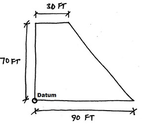
14. Locate the center of mass relative to the datum.
(a) x-bar = 45 ft, y-bar = 35 ft
(b) x-bar = 29.2 ft, y-bar = 32.5 ft
(c) x-bar = 25 ft, y-bar = 27 ft
(d) x-bar = 32.5 ft, y-bar = 29.2 ft
Solution
Best answer: (d)
Explanation
Locating the center of mass is an important step in rigid diaphragm analysis. There are three main steps: 1) break the shape into rectangles and triangles and compute areas of each; 2) identify center of area for each component shape; and 3) use centroid formulas to get the coordinates for total center of mass.
Step 1 - Break shape into rectangles and triangles, and compute areas
The given shape can be divided into a rectangle on the left with an area of (30 ft)(70 ft) = 2100 ft2, and a triangle on the right with an area of (60 ft)(70 ft)(1/2) = 2100 ft2.
Step 2 - Identify center of area for each component
For the rectangle, the center of area will be 15 ft to the left of the datum, and 35 ft up from the datum (in the middle of the rectangle).
For the triangle, the center of area will be one-third of the distance away from the right legs of the triangle. It will be (30 ft) + (60 ft)/3 = 50 ft to the left of the datum, and (70 ft)/3 = 23.33 ft up from the datum.
Step 3 - Use centroid formulas to get the coordinates for center of area (mass)
The centroid formulas compute the weighted average of the centroid for each area. The distance from the left of the datum is called x-bar. It will be equal to each area multiplied by the distance of its centroid from the datum, divided by the total area:
x-bar = [(2100 ft2)(15 ft) + (2100 ft2)(50 ft)]/(2100 ft2 + 2100 ft2) = 32.5 ft.
The vertical distance to the centroid is called y-bar and is calculated in a similar way:
y-bar = [(2100 ft2)(35 ft) + (2100 ft2)(23.33 ft)]/(2100 ft2 + 2100 ft2) = 29.2 ft.
The best answer is (d)
Watch out for a harder version of this problem!
The book Seismic Principles, is the ultimate resource to help you as you are preparing for and taking the real exam. Section 5.2 of Seismic Principles provides two additional examples for how to compute centroids (Examples 5.4 and 5.5). Example 5.6 in Seismic Principles shows what to do when wall weights are significant and need to be considered in the centroid calculation.
15. Which of the following is not true about backing bars in steel moment frame connections?
(a) They were left in place in connections built in the 1970s and 1980s.
(b) They can be removed.
(c) They can act as a fracture trigger.
(d) They are designed to assist in transferring loads between the beam and column.
Solution
Best answer: (d)
Explanation
Backing bars are used to facilitate welding, and are not intended for transferring loads. Answer is (d) is not true.
Did you get this problem wrong?
The book Seismic Principles is the ultimate resource to help you as you are preparing for and taking the real exam. Section 10.5 of Seismic Principles has a figure that shows what backing bars look like and explains how they may impact the performance of steel moment frames.
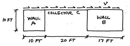
16. Wall A and Wall B are cantilever concrete walls with the same thickness. The distributed shear force, v, is 1 k/ft.
What is the shear force in Wall A?
(a) 12.7 kips
(b) 14.6 kips
(c) 23.5 kips
(d) 34.3 kips
Solution
Best answer: (a)
Explanation
There are three steps to this problem: 1) determine the total force resisted by both walls; 2) determine the rigidity of each wall and the total rigidity; 3) calculate force in Wall A based on percentage of rigidity.
Step 1 - Calculate total force resisted by both walls
The distributed lateral force is given as v = 1 k/ft, acting over a total length of 47 ft. So the total lateral force resisted by both walls is (1 k/ft)(47 ft) = 47 kips.
Step 2 - Determine the rigidity of each wall and the total rigidity
The rigidity, R, of a cantilever wall is determined with the formula:
R = 1/[0.4(h/d)3+0.3(h/d)], where h is the wall height and d is the length.
The rigidity of Walls A and B are:
RA = 1/[0.4(10/10)3 + 0.3(10/10)] = 1.43
RB = 1/[0.4(10/17)3 + 0.3(10/17)] = 3.88
The total rigidity for Walls A and B is: 1.43 + 3.88 = 5.31.
Step 3 - Calculate force in Wall A based on percentage of rigidity
The percentage of the total rigidity in Wall A is: 1.43/5.31 = 26.93%.
That means that Wall A will resist 26.93% of the total lateral force.
The shear force in Wall A is (0.2693)(47 kips) = 12.7 kips
The best answer is (a).
Did you get this problem wrong?
The book Seismic Principles is the ultimate resource to help you as you are preparing for and taking the real exam. Section 4.6 in Seismic Principles explains the concept of rigidity and the procedure that was used above. Examples 4.11, 4.12, 5.9, 5.12, and 5.13 demonstrate how to use rigidity of obtain wall forces.
17. A site has Ss=0.75g and S1=0.35g. The average shear wave velocity in the top 100 ft of soil is 2000 ft/s. What is SM1 for the site?
(a) 0.47 g
(b) 0.51 g
(c) 0.58 g
(d) 0.64 g
Solution
Best answer: (b)
Explanation
This problem can be solved in three steps: 1) determine the Site Class (based on the shear wave velocity), 2) calculate the site coefficient, 3) calculate SM1.
Step 1 - Determine the Site Class
The procedure for determining the site class is given in Chapter 20 of ASCE 7 (Table 20.3-1). For a site with an average shear wave velocity of 2000 ft/s in the upper 100 ft, Table 20.3-1 indicates Site Class C.
Step 2 - Determine the site coefficient
There are tables in the CBC and ASCE 7 (same tables) for determining the site coefficient, Fv, based on the Site Class and the value of S1. In the CBC it is Table 1613.3.6(2).
From the table, Fv is equal to 1.45 for Site Class C and S1 = 0.35 (interpolating from the table between 0.3 and 0.4).
Step 3 - Calculating SM1
SM1 is simply the site coefficient Fv multiplied by S1.
SM1 = (1.45)(0.35g) = 0.51g
The best answer is (b).
Did you get this problem wrong?
The book Seismic Principles is the ultimate resource to help you as you are preparing for and taking the real exam. The various tables you need for this problem are all provided in one spot. A version of Table 20.3-1 is provided in Section 3.4 of Seismic Principles. A version of the Table 1613.3.6(2) is provided in Section 3.5 of Seismic Principles.
18. A one-story retail building (30 ft tall) will be built on a site with SDS=0.2g, SD1=0.1g, and Site Class D.
Which of the following seismic force-resisting systems can be used?
(a) Ordinary reinforced concrete shear walls
(b) Special reinforced masonry walls
(c) Ordinary reinforced masonry shear walls
(d) All of the above
Solution
Best answer: (d)
Explanation
To solve this problem you need to: 1) identify the Risk Category for the building, 2) identify the Seismic Design Category (SDC) for the building, and 3) check which seismic force-resisting systems (SFRSs) can be used for the building based on the Seismic Design Category.
Step 1 - Identify the Risk Category
Table 1604.5 in the California Building Code (CBC) can be used to identify the Risk Category. The Risk Category depends on what the building is going to be used for. From Table 1604.5, the Risk Category for a typical retail building will be II.
Step 2 - Identify the Seismic Design Category
The procedures and tables for determining the Seismic Design Category are found in Section 1613.3.5 of the CBC. The Seismic Design Category is a function of the Risk Category and the potential for ground shaking (SDS, SD1). Based on the SDS and SD1 values that were given, and Risk Category II, the building will be in Seismic Design Category B.
Step 3 - Check appropriate Seismic Force-Resisting Systems
Table 12.2-1 in ASCE 7-10 list restrictions for use for various Seismic Force Resisting Systems. For Seismic Design Category B, there are no restrictions for any of the systems. Therefore, "All of the above" is the correct answer.
Did you get this question wrong?
The book Seismic Principles, is the ultimate resource to help you as you are preparing for and taking the real exam. An explanation of Risk Categories and an abbreviated version of CBC Table 1604.5 can be found in Section 3.7 of Seismic Principles. An explanation of Seismic Design Categories is found in Section 3.8 of Seismic Principles. An explanation of restrictions and an abbreviated version of Table 12.2-1 are found in Section 3.9 of Seismic Principles.
19. Is the layout shown below permissible if the diaphragm is rigid?
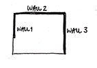
(a) Yes, because rigid diaphragms can cantilever.
(b) No, because at least two walls are required in each direction of loading.
(c) No, because rigid diaphragms require interior walls or frames.
(d) No, because rigid diaphragms cannot be used with shear walls.
Solution
Best answer: (a)
Explanation
Rigid diaphragms can cantilever, and the other statements are not true.
The best answer is (a).
Did you get this problem wrong?
You are not alone. Very few students learn anything about diaphragms as part of their undergraduate education. Chapter 5 of Seismic Principles will take you step-by-step through the procedures associated with rigid diaphragm analysis and design. Section 5.8 of Seismic Principles and Example 5.16 deal with cantilevered diaphragms.
20. A 2-story office building has steel eccentrically braced frames for the seismic force-resisting system. Each story is 13 ft tall.
What is the story drift limit for the building?
a) There is no story drift limit for this type of building.
b) 2.1 inches
c) 3.9 inches
d) 7.8 inches
Solution
Best answer: (c)
Explanation
Drift limits depend on the Risk Category for the building, the lateral force-resisting system, and the story height. This problem can be solved in three steps: 1) determine the Risk Category, 2) look up the drift limit formula from the table, 3) calculate the drift limit.
Step 1 - Determine the Risk Category
Table 1604.5 in the California Building Code (CBC) can be used to identify the Risk Category. The Risk Category depends on what the building is going to be used for. From Table 1604.5, the Risk Category for a regular office building will be II.
Step 2 - Look up the drift limit
Table 12.12-1 in ASCE 7-10 specifies story drift limit formulas for different types of structures. A building with steel eccentrically braced frame falls under the category of: "structures, other than masonry shear walls, four stories or less...". Such a building, with Risk Category II, has a drift limit of 0.025hsx from the table, where hsx is the story height.
Step 3 - Calculate the drift limit
The drift limit is: (0.025)(13 ft * 12 in./ft) = 3.9 in.
The best answer is (c).
Did you get this problem wrong?
The book Seismic Principles is the ultimate resource for the exam. Look at the examples in Section 6.11 of Seismic Principles if you are having trouble calculating drift limits. Get your own copy of the book so you have these examples with you when you take the test.
